Course 1 - Electricity
First Part
Electricity is a form of energy that results from the movement of electrons. It powers bulbs 💡, fans, TVs, phones, etc.
There are different types: static and current electricity. We'll explore them now!
Static Electricity 1
Most people don’t know that there are two types of electricity. Static and Current electricity
In this section I will teach you about static electricity. By any means possible🤗👌.
What is static electricity?
Static electricity is the accumulation of electric charge on the surface of an object.
It is usually caused by the transfer of electrons from object to object.
Keep in mind that it is only electrons can move.
Every object is made up of atoms.
An atom is made up of sub-particles which are:
Protons (+),
Neutrons (0) and,
Electrons (-)
Ordinarily, an object is electrically neutral meaning the number of protons equals the number of electrons. Therefore, there is a balance.
Now an object is electrically charged when there becomes an imbalance, meaning the number of protons and electrons becomes different.
Ways of charging objects.
1. By friction: When two different objects are rubbed together, it causes electrons to transfer.
This makes the two objects become electrically charged. i.e. One is negatively
charged and the other is positively charged.
2. By conduction or contact: Direct contact between a charged object and a neutral
object causes electron transfer.
3. Induction: A charged object brought neutral conductor can cause shift in the
arrangement of protons and electrons in that object.
Induction only causes polarization unless grounded.
Which object loses electrons?
The triboelectric series is a list of materials ranked according to their tendency to lose electrons.
Below are materials with strong tendency to lose electrons
1. Human skin
2. Human hair
3. Glass
4. Wool
5. Nylon
6. Fur
7. Silk
8. Cotton
9. Paper
10. Leather
Jot down what you learnt.
Static electricity 2
The Gold Leaf Electroscope
The gold leaf electroscope is an instrument used in detecting small charges or static electricity in objects.

It consists of a metal rod with a metal disk or ball at the top and two thin, lightweight gold leaves attached at the bottom.
The rod and leaves are enclosed in a glass case to protect them from air currents and external interference.
How does it work?
1. When a charged object is brought near the metal disk, the charge is transferred to the disk and down the metal rod to the gold leaves.
2. If the charge is positive, electrons in the gold leaves are attracted to the disk, leaving the leaves positively charged. Since like charges repel, the gold leaves diverge.
3. If the charge is negative, excess electrons flow to the gold leaves, causing them to become negatively charged and repel each other.
4. The degree of divergence of the gold leaves indicates the amount of charge present.
Conductors
Conductors are materials that allows the free flow of electrons through them.
Examples are:
Gold, Aluminium, Copper, Silver, Carbon, Water (salt water), Iron, Mercury, Platinum, Antimony, Brass, etc.
Make sure you jot down what you learnt😁.
Static electricity 3
Electric field (charges)
An electric field is an invisible area around a charged object.
You must know that forces are split into two: Contact forces and non-contact forces.
Contact forces requires physical contact for it to be felt while non-contact force or FIELD forces does not need physical contact for it to be felt.
So,
An electric field is the region where you would feel electricity.
Now we know what an electric field is but how do we know the direction of an electric field?
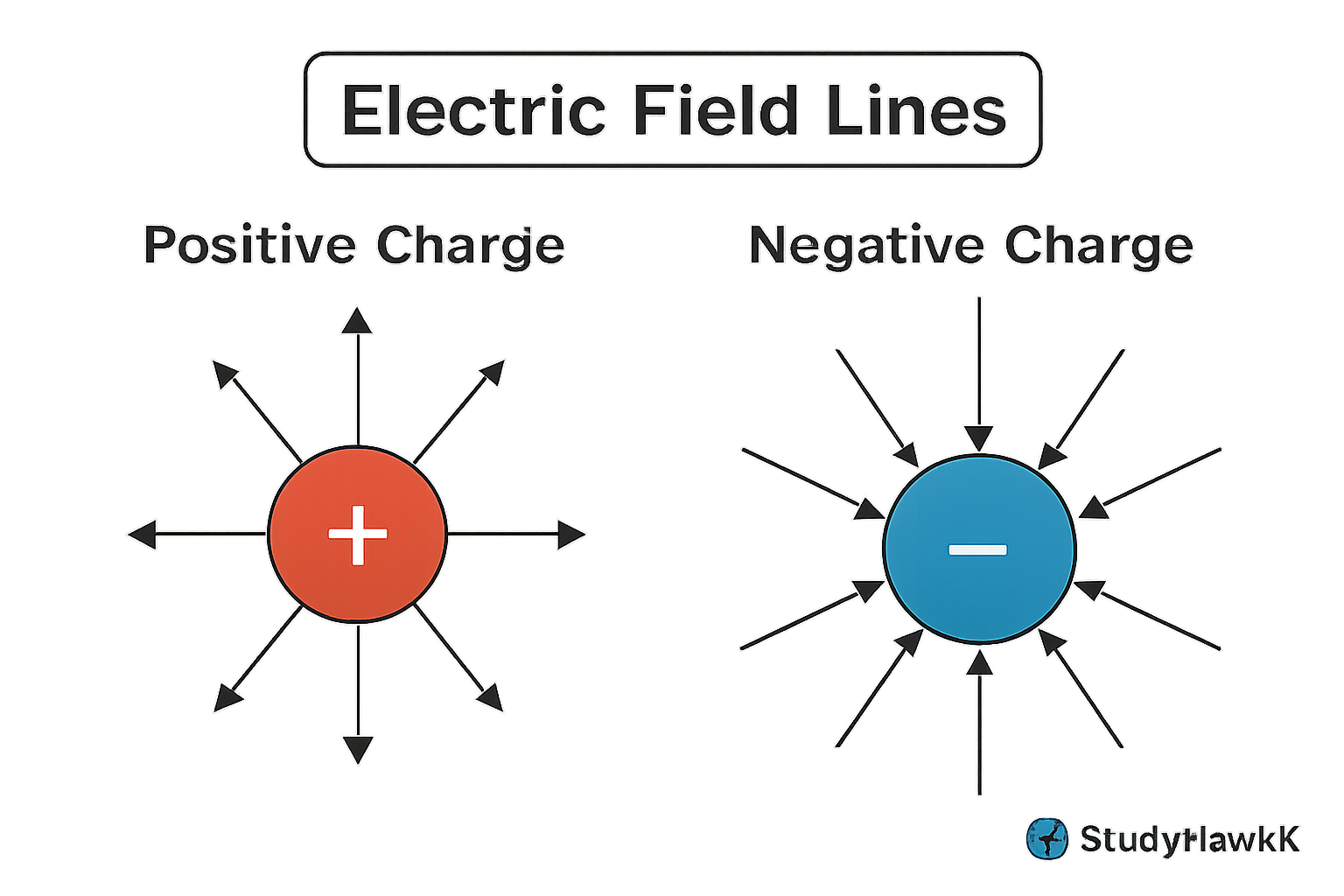
We use Electric field lines.
What is electric field line?
Electric field lines are imaginary lines used to visualize the direction and strength of an electric field around charged objects.
They show the path a positive test charge would follow if placed in the field.
The lines point away from positive charges and toward negative charges. The closer the lines are, the stronger the electric field in that region.
Now let’s study how to determine the strength of an electric field.
Electric field intensity
Electric field intensity is a measure of the strength of an electric field at a point.
It tells you how much force a positive test charge would feel if placed at that point.
The greater the intensity, the stronger the force on the charge.
It depends on the amount of charge creating the field and the distance from that charge—closer distances mean higher intensity.
Electric field intensity can be referred to as the force of an electric field per unit charge.
Mathematically,
E = F / Q NC-1
E = Electric field intensity in Newtons per coulomb
F = Electric force in Newton
Q = Electric charge in Coulombs
Practice questions
1. A charge of 5C experiences a force of 10N when placed in an electric field. Calculate the electric field intensity at that point.
E =? NC-1
F = 10N
Q = 5C
E = F / Q
E = 10 / 5 = 2
Therefore, the electric field intensity at that point is 2NC-1//
2. An electric field has an intensity of 20N/C. If a charge of 2C is placed in this field, what force will it experience?
E = F / Q
F = E x Q
F = 20 x 2
F = 40
Therefore, the electric force the charge will experience is 40N//
Now that we know how to determine the intensity of an electric field, and the force felt when a test charge enters an electric field.
Let’s look at how to determine the electrical force that exists between two charged objects.
Jot down what you learnt.
Course 1 - First Test
You have 15 questions
Read the questions carefully, then answer.
Capacitors and Capacitance
What the he😌🤔ck is even a capacitor?
A capacitor is a device that stores electric charges.
It is made up of two conductors separated by an insulating material. It's main purpose is to store electric charges. It might have the same function as a battery, but they don’t work the same way.
Batteries use chemicals and chemical reactions but, Capacitors use the potential difference(voltage) between the two conductors to store charge.
Another big difference between a capacitor and a battery is that a capacitor releases the electricity at once and for a short time.
I advise you search for pictures of capacitors.
And as much we would hate to do this,
Watch this video from Khan academy
Then come back and read again🦾.
Capacitance
Where C = Capacitance in farads, F
V = Voltage in volts, V
Q = Quantity of charge, C
Capacitance is the measure of the amount of charge a capacitor can store per unit voltage.
It is measured in farads, F.
Mathematically,
C = Q / V
Q = CV
V = Q / C
Capacitance is directly proportional to the area. Meaning the larger the area the more the electric charge stored.
Capacitance is inversely proportional to the distance between the two plates. Meaning the greater the distance the lower the amount of charge can be stored (capacitance).
C= ϵA / d
ϵo = 8.854 x 10⁻¹²(permittivity in a vacuum)
"It has been a lot but I know you are learning. Before we move into the next sections, after you jot down what you learnt from this section. Do a personal revision on all you’ve learnt. Keep working hard, you are the best😁"
From “Oriarebun Princeton” – Creator of StudyHawkX.
Capacitors and Capacitance 2
Work to do
1. A capacitor with a capacitance of 5μF is connected to a 9V battery. Calculate the charge stored on the capacitor.
C = 5μF = 5×10⁻⁶F
V = 9V
C = Q / V
Q = CV
Substitute the values:
Q = (5×10-6) × 9
Q = (5 x 9) x 10-6
Q = 45 x 10-6
Q = 45μC (microcoulombs)
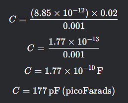
2. A parallel-plate capacitor has plates with an area of 0.02m^2 and a separation of 0.001m If the dielectric material between the plates has a permittivity of ϵ = 8.85×10^-12 F / m, calculate the capacitance.
The formula for the capacitance of a parallel-plate capacitor is:
C= ϵA / d
ϵ= 8.85×10⁻¹² F/m
A = 0.02 m2
D = 0.0001 m
Substitute the values:
3. A capacitor has a capacitance of 10μF and is charged to a voltage of 12V. Calculate the energy stored in the capacitor.
Did you get it?
It seems we did not teach you when explaining capacitors and capacitance. The energy stored in a capacitor is denoted by U
And,
U = ½CV2
C = 10μF = 10x10-6F
V = 12V
Substitute the values:
U = ½ x 10x10-6 x 122
U = 5x10-6 x 144
U = (5 x 144) x 106
U = 720 × 10-6J
Therefore U = 720μJ(microjoules) //
🦾First Part😁Done🦾
Second Part
Current Electricity 1
At the start we said that most people don’t know that there are two types of electricity.
Static electricity and Current electricity.
We talked about static electricity and how it is just the accumulation and release of electric charges.
So,
What is Current electricity?
Current electricity is the rate of flow of electric charges(electrons) through a circuit.
Well, what does that mean🤔?
When we connect a wire to a battery and a light bulb,
The battery causes electrons to flow through the wire and through the light bulb causing it to glow.
That entire setup is what we call a CIRCUIT.
A circuit is a complete closed path that allows electric charges to flow.
1. What is Electric Current?
- Electric current is the flow of electric charges. In most circuits, these charges are electrons.
- The unit of current is the ampere (A), which measures how many charges flow per second. For example, 1 ampere means 1 coulomb of charge flows every second.
2. What Causes the Flow of Electrons?
- The battery acts like a pump, creating a voltage (or potential difference) that pushes electrons through the circuit.
- Voltage is like the "pressure" that makes electrons move.
3. What Happens in the Light Bulb?
- As electrons flow through the filament of the light bulb, they collide with atoms, causing the filament to heat up and glow. This is how the bulb produces light.
4. Why Does the Circuit Need to Be Closed?
- Electrons need a complete path to flow. If there’s a break in the circuit (like an open switch), the electrons stop flowing, and the light bulb turns off.
Current is measured in Amperes, A.
Mathematically,
I = Q / T
Where I = Current in amperes
Q = Quantity of charge in coulombs
T = Time in seconds
Again,
I = Q /T
Work to do
1. A wire carries a total charge of 60C (coulombs) in 10seconds. Calculate the electric current flowing through the wire.
I =?
Q = 60C
T = 10s
Substitute the values:
I = Q / T
I = 60 / 10
I = 6A
Therefore, the electric current flowing through the circuit is 6 amperes//
2. A conducting wire carries a total charge of 250millicoulombs(mC) in 5seconds. Calculate the electric current flowing through the wire in amperes.
I =?
Q = 250mC
We need to get the answer in amperes if we don’t convert Q to ordinary coulombs, we would get millicoulomb instead.
Q = 250mC = 0.25C
T = 5s
I = Q / T
Substitute the values
I = 0.25 / 5
I = 0.05 A//
Measuring instruments
1. Ammeter: This device is used to measure currents in a circuit.
2. Voltmeter: This device is used to measure voltage or potential difference in a battery.
3. Potentiometer: This device is also used to measure e.m.f , p.d or voltage but with an higher degree of accuracy.
4. Galvanometer: Galvanometers are used to measure small currents from the range of milliamperes (10^-3) to micro-amperes (10^-6).
5. Centre-zero galvanometer: Centre-zero galvanometers are basically special galvanometer, which because they have zero in the center which provides the direction of the current.
You are locked In fr🤫 Jot down what you learnt🦅
Current electricity 2
Resistance and Ohms law
Resistance is the ability of a substance to oppose or resist the flow of current.
Insulators have high resistance, while conductors have low.
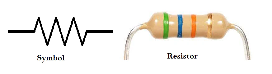
A resistor is a device used to control current by adding resistance. There are fixed resistors and variable ones like the rheostat and potentiometer.
If we want to find the resistivity of a resistor, we use this formula:
P = RA / L
P = Resistivity
R = Resistance
A = Cross-sectional area of the wire
L = Length of the wire
ALSO
R = PL / A
OHMS LAW
Ohm’s Law shows the relationship between Voltage (V), Current (I), and Resistance (R) in a circuit.
Ohms law states the electric current passing through a metallic conductor at a constant temperature is directly proportional to the potential difference applied between its ends.
This means that if you increase the voltage, more current will flow, unless the resistance also increases. Likewise, increasing resistance will reduce the current if the voltage stays the same.
Mathematically,
V = I × R
V = IR
Where:
- V = Voltage (in volts)
- I = Current (in amperes)
- R = Resistance (in ohms)
You can rearrange it based on what you want to find:
1. To find current: I = V / R
2. To find resistance: R = V / I
3. To find voltage: V = I X R
Jot down what you learnt🌟🌟
Practice questions
Work to do
1. A resistor is made of a material with resistivity ρ=1.1×10⁻⁶Ωm.The resistor has a length of 0.5m and a cross-sectional area of 2×10⁻⁶m2.
Calculate the resistance of the resistor.
ρ = 1.1×10⁻⁶Ωm
L = 0.5m
2×10⁻⁶m2
R =?
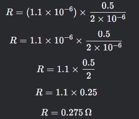
Another way you could solve it, is by first converting the values to decimal then use a calculator to do it straight.
R = 0.0000011 x 0.5 / 0.000002
R = 0.275Ω //
2. A current of 0.5A flows through a resistor with a resistance of 10Ω. Calculate the voltage across the resistor.
Ohms law states that V = IR
V =?
I = 0.5 A
R = 10 Ω
Substitute the values
V = 0.5 x 10
V = 5
Therefore, the voltage across the resistor is 5 volts//
3. A voltage of 12V is applied across a resistor with a resistance of 6Ω. Calculate the current flowing through the resistor.
V = IR
I = V / R
I =?
V = 12V
R = 6Ω
Substitute the values
I = 12 / 6
I = 2A
Therefore, the current flowing through the resistor is 2 Amperes//
4. A current of 0.2A flows through a resistor with a resistance of 50Ω. Calculate the power dissipated in the resistor.
The formula for power dissipated in a resistor is:
P = I2R
I = 0.2A
R = 50Ω
Substitute the values
P = 0.22 x 50
P = 0.04 x 50
P = 2W
Therefore, the power dissipated in the resistor is 2 watts//
5. A voltage of 9V is applied across a resistor, and a current of 3A flows through it. Calculate the resistance of the resistor.
According to ohms law, V = IR
R = V / I
But for those that don’t know how to make something the subject pf the formula I will do it straight from V = IR
V = 9V
I = 3A
R =?
Substitute the values
9 = 3R
Divide both sides by coefficient of R
9 / 3 = 3R / 3
3 = R
R = 3Ω //
“If I say I’m not tired, I am lying. So as not to make your efforts and mine worthless let’s not give up😁.”
From “Oriarebun Princeton” – Creator of StudyHawkX.
Jot down what you learnt.
Course 1 - Second Test
You have 10 questions
Read the questions carefully, then answer.
Resistors and Capacitors
(series and parallel connection)
Resistors (Oppose Current Flow)
Resistors resist the flow of electric current (like a narrow pipe resisting water flow).
It is measured in ohms Ω.
1. Resistors in Series (One after another)
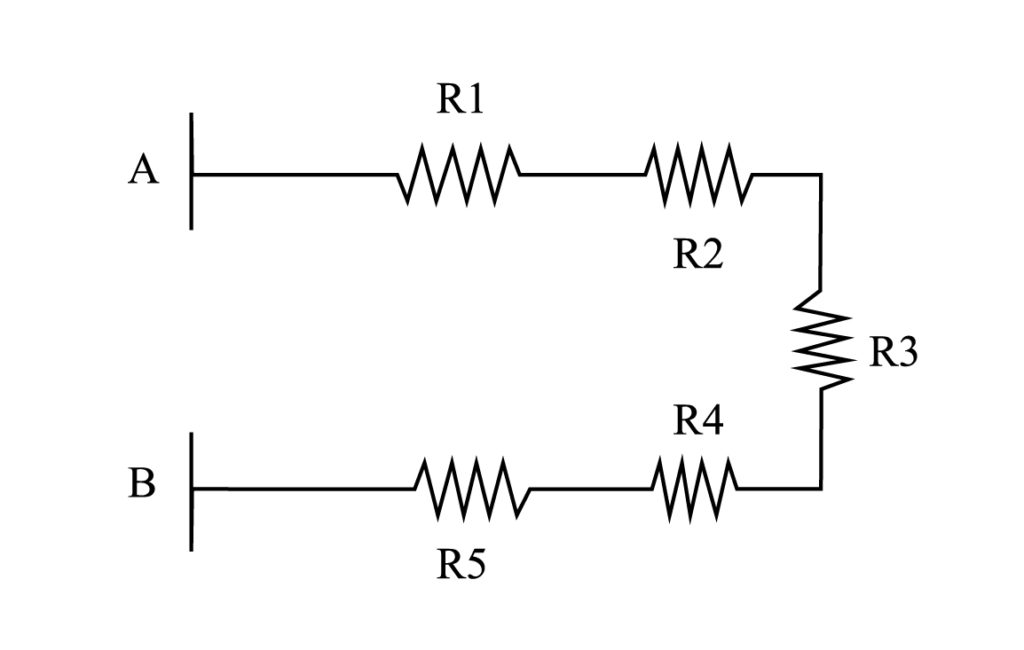
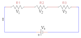
• The resistors are connected together one after the other, as seen from the images.
• Current (I): Same through all resistors.
• Total Resistance (Rₜₒₜₐₗ): Just add them up.
Rtotal = R1 + R2 + R3 +…
• Why? The current has to fight through each resistor one by one, making total resistance higher.
Example:
If R1= 2Ω and R2 = 3Ω are in series:
Rtotal = 2 + 3 = 5Ω//
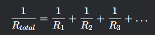
2. Resistors in Parallel (Side by side)
Do you see the difference?
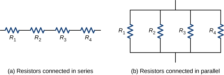
• The resistors are connected side by side providing different paths for current flow.
• Voltage (V): Same across all resistors.
• Total Resistance (Rₜₒₜₐₗ): Less than the smallest resistor
1/Rtotal = 1/ R1 + 1/R2 + 1/R3 + …
Example:
If R1 = 2Ω and R2 = 2Ω are in parallel:
1/Rtotal = 1/R1 + 1/R2
1/R = 1/2 + 1/3
1/R = 5 /6
Invert it
R = 6 / 5
R = 1.2//
• Why? Current has multiple paths, so resistance decreases (like more pipes letting more water flow).
Capacitors (store charges)
A capacitor is a device that stores electric charges.
It is measured in farads F.
The total capacitance of capacitance connected in series and parallel are opposite to resistors connection.
In series:
1/ Ctotal = 1 / c1 + 1/c2…
Example:
If C1 = 2F and C2 = 2F are in series:
1/ctotal = ½ + ½ = 1F//
In parallel:
Ctotal = c1 + c2…
Example:
If C1 = 2F and C2 = 3F are in parallel:
Ctotal = 2 + 3 =5F//
“With that we are done with the course electricity, how does it feel to fully understand the concept of electricity Well, not fully but you’ve done your best. Now take the final test and move on to course 2 MOTION I pray you pass.”
From “Oriarebun Princeton” – Creator of StudyHawkX.
Physics Course 1 Final Test
Read the questions carefully, then answer. You can do it.